制御回路 |
Control Circuit |
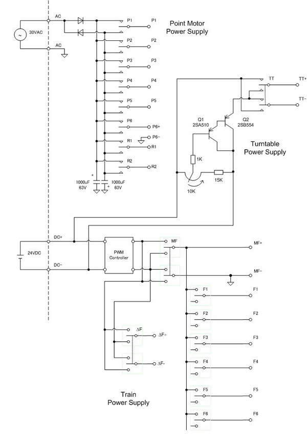
Control circuit is shown in following diagram. Circuit common (shown as inverted triangle in the drawing) is connected to one side of the rail (in my case inside the endless). With this arrangement only one wire is required to a point motor. Other side is just taken from inside rail nearby the point motor. However to allow this arrangement train and point motor supplies must be isolated by transformers each other.
制御回路は下の図面のようになっています。ポイントマシンと車両用の電源は逆三角形で示された共通母線につながっています。私の場合エンドレスの内側のレール。このため、各ポイントマシンには電線は一本だけ這わせればよく。他の側は内側のレールから取ります。こうするためには、ポイントマシン用と車両用の電源はお互い別のトランスで絶縁されていなければなりません。
Circuit |
Description |
説明 |
Point Motor |
+ and - polarities for point motor are obtained by half wave rectification. The switches are spring-return type SPDT. |
ポイントマシンの電源は30VACから半波整流され、+およびーの極性を得ています。スイッチはスプリングリターンのSPDT。 未使用時にはコンデンサが約45Vにピークチャージされるているので、スイッチオンの瞬間には強力な電流が流れポイントマシンの動作を確実にします。その後コンデンサの放電とともに30V以下に落ちるはずです。(計っていません。) |
Train |
This is fed from LGB power pack always set at its maximum voltage. I made a PWM regulator to control trains. Refer to "PWM Speed Controller" for details. |
最大電圧にセットされたLGBのパワーパックから供給されています。車両のスピードは自作のPWMコントローラで行っています。「PWMパワーパック」参照。 |
Turntable |
The power to the turntable is pinched from train power. I made a voltage regulator to drop the voltage to 1.5 to 3V required by turntable motor. The voltage is set by a potentiometer. |
ターンテーブルは1.5から3Vが必要です。定電圧レギュレータ(PNPトランジスタ2個をダーリントン接続)を作りました。 |