電動ポイント・マシン (1) |
Electric Actuators (1) |
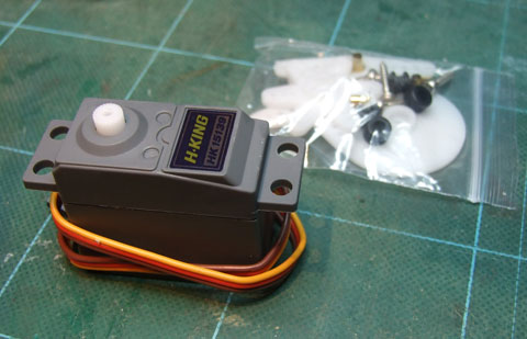 |
Pneumatic actuators I made before have a fatal problem and I decided to give them up. All the tubing and equipment are pressurised all time and only one air leakage point may wreck the whole system. So I decided to develop electrical actuators. I made an experiment of torque motor modified from a servo for my friend. Obviously normal servos are not suitable for outdoor use. Some sort of waterproof servos are required. This is the waterproof servo I used. It is call "waterproof", but obviously not submergible. I think its IP rating is IP64 or so. Anyway it is very cheap only US$3.81. 以前作った空圧ポイント・マシンは致命的な欠点があり諦めた。全てのパイピングと機器に常時圧力がかかっているので一箇所でも漏れているとダメなのだ。と、言うことで手慣れた電動のものを作ることにする。以前友人に頼まれて実験したサーボ改造のトルクモータを使うことにする。当然通常のサーボではダメで防水形が必要である。これが防水型のサーボ。防水と言っても水中で使用できるような代物ではない。IP64ってとこかな?たったのUS$3.81だ。 |
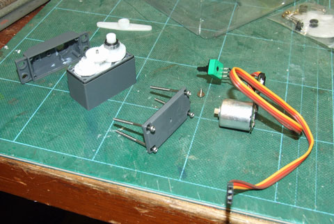 |
Disassembled servo. Control PC board on the right is not required and to be removed from the motor. サーボをばらしたところ。右にある制御基板は不要なので、モーターから分離する。 |
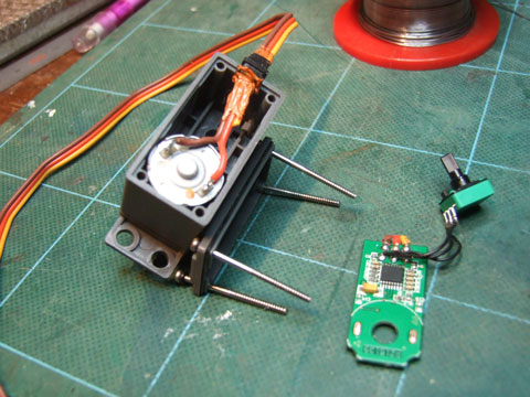 |
Power supply wirings are directly soldered to the motor terminals. Waterproofing at the wiring grommet seemed poor. So I filled the grommet with silicone sealant. The right is the control PCB and potentiometer made redundant. 電源線を直接モータにハンダ付け。電線のグロメットのところの防水が怪しそうだったのでシリコン・シーラントを塗っておく。右のが不要になった制御基板とポテンショ。 |
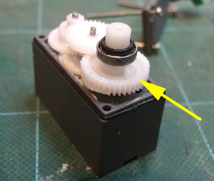 |
I removed the stopper pin on the final gear to make the servo free-running. However it was not necessary because point actuators move only in limited stroke. An O-ring is seen on output shaft showing this servo is waterproof. 連続回転できるように回転ストッパのボッチ(矢印)切り取った。でも考えてみればポイントマシンなので連続回転できなくてもOK。切り取らなくても良かった。出力軸にO-リングが入っており一応防水仕様になっているのがわかる。 |
I drove the modified servo from a constant current regulator. It works as a toque motor. 定電流装置から駆動するとこのようにトルクモータになる。 |
|
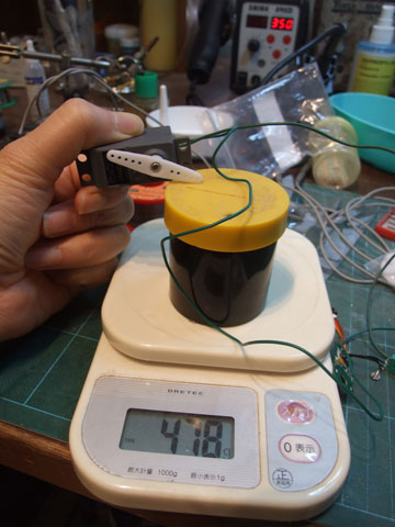 |
With 100mA armature current it generated about 500gF at the tip of the arm. It should be more than enough. 100mA流してアームの先端で約500gF。十分であろう。 |
 |
Temperature rise of the motor was measured. I fixed the servo on a vice to make the arm stalled and kept flowing 100mA current. 温度上昇を測定する。サーボをバイスにアームが回らないように固定。100mAを流し続ける。 |
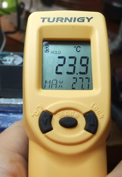 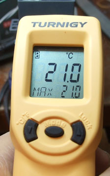 |
I left it for 10 minutes or so and measured the motor temperature by a radiation thermometer. Motor temperature is shown in lower part of display as MAX and it was 27.7℃. Ambient temperature was 21℃ and temperature rise was 6.7℃. This temperature rise is acceptable. This radiation thermometer is also very cheap, only US$21.7. It is quite handy for cooking. 10分ほど放置しモータ温度を放射温度計で測定。下のMAXがモータ温度27.7℃。外気温は21℃。6.7℃の上昇。問題無いだろう。ちなみにこの放射温度計も安い。US$21.7。料理にも使える。 |
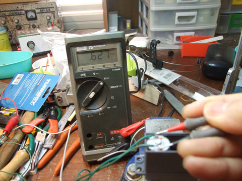 |
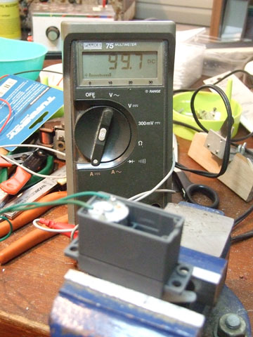
After 10 minutes under stall condition with 100mA current, I measured motor terminal voltage. It was 0.63V. The winding resistance may change by temperature and the resistance should be measured after temperature saturation. The resistance required to limit the current to 100mA with 5V power supply is: (5-0.63)/0.1=43.7Ω, Heat dissipation of about 0.5W. A resistor with rating of 1W 47Ω would be OK. The resistors should be de-rated by half for longer life and preventing hot surface. I thought to accommodate the resistor inside the servo, but 0.5W would be too large to keep the servo under reasonable temperature. The temperature rise of the motor was 7℃ with 0.063W power dissipation. I will install the resisters outside.
100mAを流してストール時10分経過後のモータ電圧降下は0.63V。温度上昇とともに巻線抵抗値が変化するので温度が飽和した時に測るべきである。5V駆動時100mAに抑えるために必要な直列抵抗値は: (5-0.63)/0.1=43.7Ω 発生熱量0.5W弱。 1W 47Ωの抵抗でOKであろう。抵抗器は少なくとも1/2くらいにディレーティングすべきである。モータの発熱は0.063Wで約7℃上昇。抵抗はサーボ内に収めようと思っていたが0.5W発熱では温度が上がりすぎるであろう。外付けにする。 |