ジョイ式 |
Joy Valve Gear |
One of my Japanese friends showed photos of an old steam loco with Webb type Joy valve gear in his blog. When I looked at this I wondered how Joy valve gear worked. Following is my though about this subject. Movie on the left is taken from "Valve Gear Simulator". ジョイ式の動作原理がどんなものか考えたこともなかったんですが、あるきっかけから気になりだしてしまった。以下に自分なりに考えた結果を述べておく。左の動画はバルブギア・シミュレータで動かしたものです。 |
|
 |
|
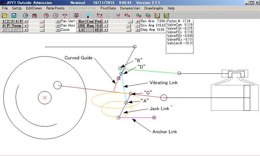
Above is the link diagram of Joy valve gear. Red crosses are anchor point to the frame. Very basic function of a valve gear is to move the valve in 90 degree phase difference against the piston. If efficiency is not a matter this arrangement only can run a steam engine. However to improve the efficiency valves should have "Lap" to allow cut-off. Also "Lead" is necessary to admit the steam slightly before the piston reaches its dead-points. So Lap+Lead will be an advance angle of the valve. It is easy in case of Stephenson type. Just rotate the eccentrics by required advance angle from 90 degrees of the con-rod pin. In case of Walschaerts type, the return crank makes 90 degree phase shift and the combination lever combines this and movement of crosshead (no phase shift) to make required valve angle, say 110 degrees (90 deg. + 20 deg. Advance). Now discuss how Joy type works. 90 degrees phase sift is taken from up-down movement of the con-rod. How the movement without phase shift is taken? It is easy by observing motion of the con-rod. Note the movement of point "C"! This point moves in larger oval shown in yellow having two components 0 degree (back and forth) and 90 degree (up and down) shifts. These components are combined together by "Vibrating Link" in the same manner as combination lever of Walschaerts. I wondered if so why "vibrating link" was not connected directly to the con-rod at point "C". If you can make the "vibrating link" very long it may be possible, but the length is quite limited. Large back-forth movement of con-rod makes this idea impractical making the operation angle of "vibrating link" too large. So "Jack Link" and Anchor Link" are provided to reduce the back-forth movement to manageable range. The movement of point "A" is shown by small yellow oval. With this arrangement up-down movement is not affected, but back-forth movement is reduced. |
上がジョイ式のリンク図。赤バツはフレームに固定。 バルブギアの一番基本的な機能はピストンから90°位相をずらしてバルブを動かす。効率とかを気にしなければこれだけで蒸気機関は動きます。効率を上げるために通常はカットオフができるようにするため弁にラップ(重なり)を付けます。さらにピストンが死点に達する少し前から蒸気の供給を開始するためにリードを付けます。ラップ+リードがバルブの進角になるわけです。 スティーブンソン式の場合は上記の進角分だけエキセントリックを90°からずらせばいいんで簡単です。ワルシャートの場合はリターンクランクで90°の位相差を作り、クロスヘッドからの位相差ゼロの動きをコンビネーション・レバーで合成し、望みの90°+進角、例えば110°とかを作るわけです。 ジョイ式ではどうしているかというと90°の位相差はメインロッドの上下動から作っています。ピストンが前後に動くときにメインロッドは上下にも動きます。これを捉えているわけですね。視点を90°変えて真上から見ればクランクの動きが90°ずれて見える。だたそれだけのことです。では位相差ゼロの動きはどうするか?これはメインロッドの動きに注目すればわかります。上図の”C"点に注目!この点は黄色で示したような楕円運動をします。そうです。”C"点からは位相差0°(前後)と90°(上下)の両方の動きが取れるのです。そしてVibrating Linkがワルシャートにおけるコンビネーション・レバーと同様の働きをし位相差90°と0°の動きを合成しているのです。ではVibrating Linkを直接”C"点に接続すればいいんじゃないかと思われるかもしれませんがダメです。Vibrating Linkがすごく長ければ直接つないでもOKです。でも、Vibrating Linkの長さはかなり短めに制限されます。上図を見ればわかりますがVibrating Linkが上の楕円に沿って動いたらどうなるでしょう?リンクの動作角が大きくなりすぎてまともに機能しなくなるでしょう。(リンクの動作角は小さいほど理想状態に近づく)そこでJack LinkとAnchor Linkで前後方向の動きだけを小さくします。”A"点は小さい楕円のように動きます。このリンク配置で上下動はほとんど変わらず前後動だけ減らせるのです。 |
 |
This is the vector diagram of the combination of the movements. It is not familiar for most people, but drawing this makes understanding much easier for me as an electrical engineer. 動きの合成を示すベクトル図です。一般人にはなんだかわからんかもしれませんが、電気系エンジニアである管理人は位相に関わるものはいつもこんな図で考えてしまうのです。 |
Webb Type Joy Valve Gear
|
|
There is a variation of Joy valve gear called Webb type. This type is not found in "Valve Gear Simulator" and I drew a link diagram. The operation principle is the same as ordinary Joy. However the method to reduce the back-forth movement at point "A" is different. In Webb type point "A" is connected to a return crank with smaller acting circle than main crank to allow pint "A" follows small yellow circle. |
ジョイ式の変種としてウェブ型と言うのがあります。Valve Gear Simulatorには入ってなかったのでリンク図をCADで描いてみました。動作原理は当然普通のジョイ式と一緒です。違いはVibrating Linkの前後動を減らす方法だけです。ウェブ型ではJack LinkとAnchor Linkの代わりに少し内側に戻したリターンクランクを使って”A"点の動きを減らしています。メインロッドの前後動からリターンクランクが内側によった分だけ動きが引き算されることになります。 |
Oval Diagram
|
|
This is the oval diagram of Joy type obtained from "Valve Gear Simulator". "2" shows forward and "3" shows reverse. As seen here there two do not match well and ovals are warped. In case of Stephenson and Walschaerts forward reverse are well overlapped with nice oval shape. In Joy type up-down movement of driver directly affects the valve timing. Also the "vibrating link" keeps moving up-down in the grooves of curved guide wearing die-blocks. Mentioned above is my own idea and no guarantee it is collect. |
これはValve Gear Simulatorが出してくれるジョイ式の楕円図です。2が前進、3が後進でズレが酷いです。楕円もいびつだし。スティーブンソンやワルシャートでは2つのきれいな楕円がほぼ重なるんですが。また、動輪の上下動でバルブ・タイミングが狂ってしまいます。さらにCurved Guideの溝の中をVibrating Linkが絶えず上下に摺動するのでダイブロックの摩耗が激しくメンテが大変なはずです。特性も良くないしメンテも大変。ワルシャートに駆逐されたのも当然でしょう。 以上は私が勝手に考えたことなので正しい保証はありません。 |

